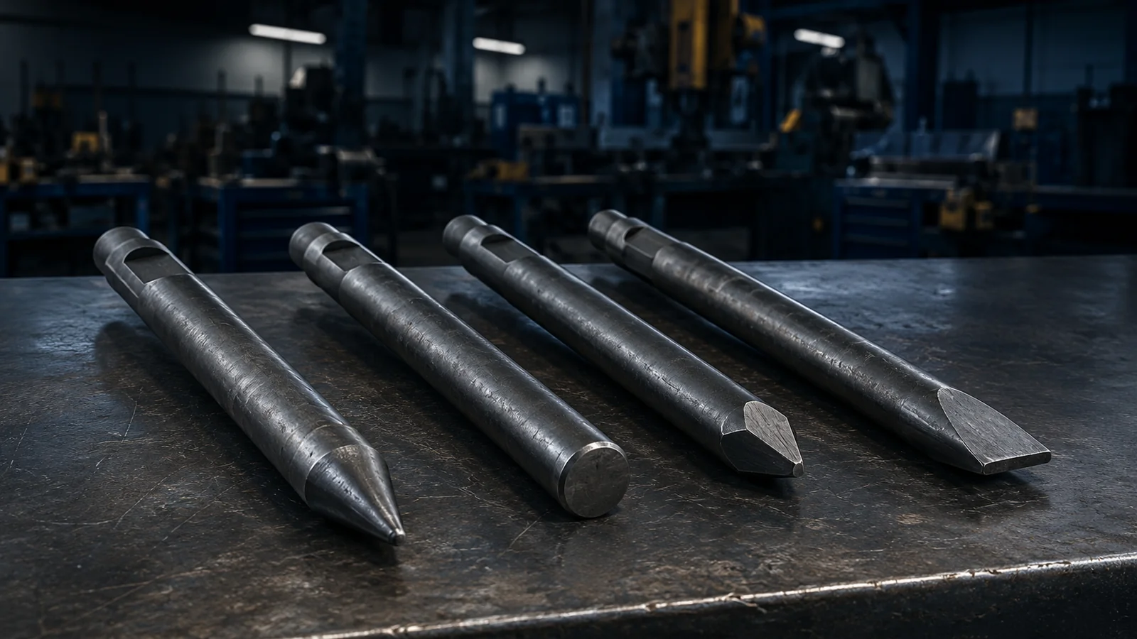

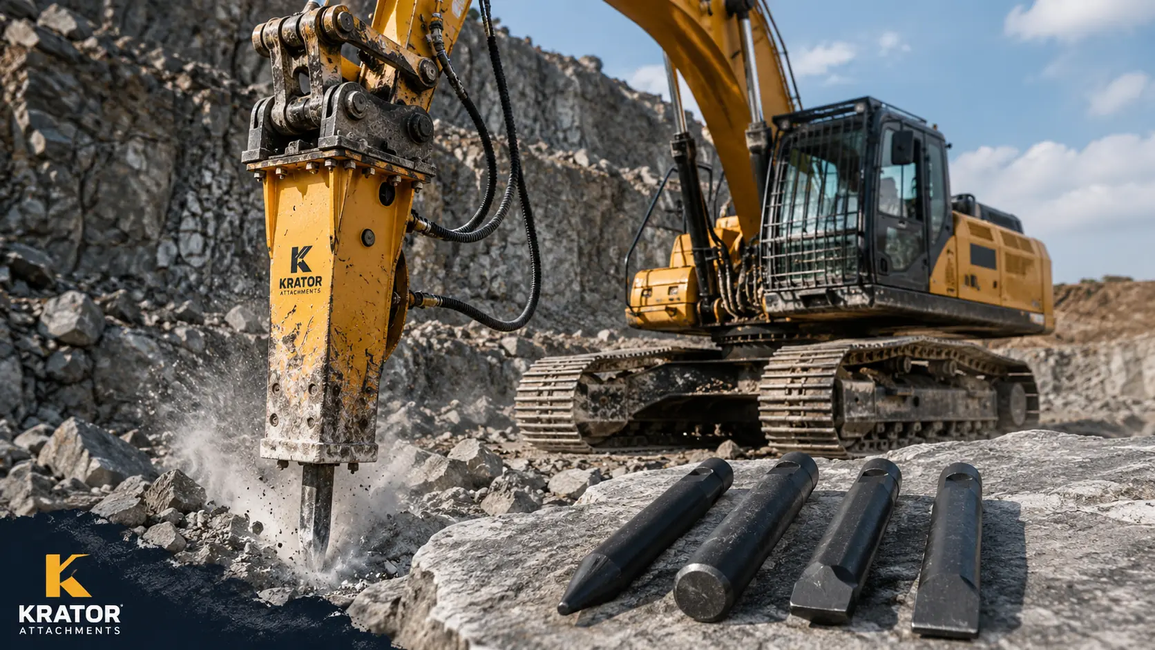
Select the working objective before selecting a tool shape. A moil point is commonly considered for concentrated penetration, a blunt tool for broad impact on some brittle blocks, and a flat chisel or wedge for controlled directional splitting. The final choice depends on material structure, breaker model, supported tool dimensions, retainer design, carrier flow and pressure, working position and safe tool behavior.
Tool Shape Is Only One Part of the Decision
A material name does not identify a working tool by itself. “Hard rock” may be massive, layered, weathered or already fractured. Concrete may be plain or reinforced. A trench may require directional control in confined access rather than simple penetration. Tool selection therefore starts with the job objective and material structure, then moves to the exact breaker and carrier.
This page answers which tool category may suit this material and job. For definitions and fitment terminology, use the hydraulic breaker chisel types guide. For complete attachment sizing, see how to choose a hydraulic breaker.
Application-Based Tool Selection Table
| Material or job | Working objective | Tool category commonly considered | Reason | Main caution | Information requiring confirmation |
|---|---|---|---|---|---|
| Hard massive rock | Initiate penetration or a fracture | Moil point; sometimes another approved pointed profile | Concentrated contact may help start local penetration | Avoid prolonged impact in one point without progress | Joints, confinement, abrasiveness, breaker model and supported tool |
| Fractured rock | Open existing weakness and reduce pieces | Moil, blunt or flat chisel may be suitable | Placement along cracks may matter more than size | Do not work among unstable fragments | Fracture pattern, support, access and exact model |
| Oversized stone | Secondary size reduction | Blunt or pointed tool | Broad impact may crush brittle stone; a point may initiate a crack | Stabilize the work area and avoid moving blocks | Brittleness, crack pattern, block support and tool availability |
| Reinforced concrete | Break the concrete matrix | Moil point or correctly oriented flat chisel | Penetration or directional splitting may expose reinforcement | A breaker tool does not safely cut reinforcing steel | Reinforcement, services, structure, breaker model and separate steel method |
| Plain concrete | Penetrate, crack or split a slab or mass | Moil point or flat chisel | Choice depends on thickness, support and desired fracture direction | Avoid side loading and unsupported collapse zones | Thickness, support, buried services, access and exact tool |
| Asphalt | Open or separate a controlled edge | Flat chisel or approved cutting profile | A defined edge may assist directional work | Confirm buried services and avoid levering | Layer structure, base material, access and tool options |
| Trenching | Controlled penetration or directional splitting | Flat or wedge-shaped tool; moil in some ground | Orientation and narrow access influence control | Side loading and prying must be avoided | Ground layers, trench geometry, services, breaker and retainer |
| Frozen ground | Initiate cracks and loosen compacted material | Moil point or approved chisel profile | Concentrated contact may start a break | Ground response and buried hazards vary | Depth, moisture, obstructions, services and exact breaker |
| Secondary breaking | Reduce already separated material | Blunt or moil point | Tool depends on whether crushing or crack initiation is needed | Stop after separation to limit blank firing | Material structure, block support and model-specific options |
| Directional splitting | Guide a fracture along an intended line | Flat chisel or wedge | The edge can be oriented to the intended split | Orientation must not create twisting or side load | Material bedding, access, tool dimensions and retainer design |
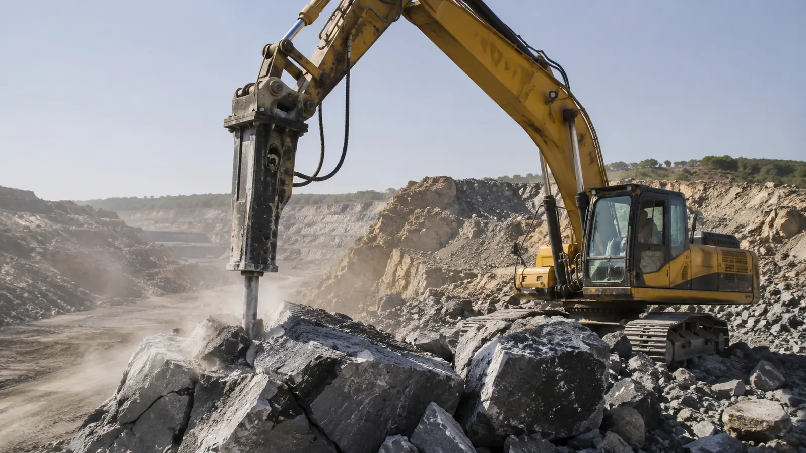
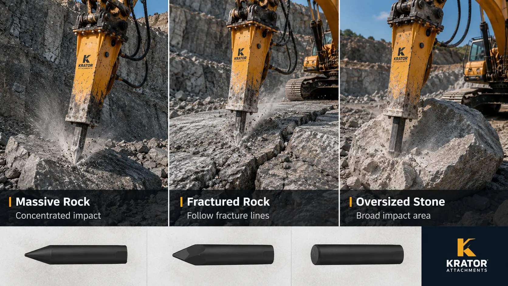
Tool Selection for Hard Massive, Fractured and Oversized Rock
Hard Massive Rock
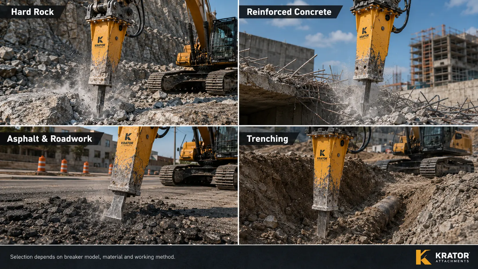
Concentrated force may be required where few joints are visible, so a moil point is commonly considered. Penetration still depends strongly on joints, bedding and confinement. A larger tool is not automatically more effective, and prolonged impact at one point should be avoided when no fracture develops. Reposition only after stopping impact and maintaining stable carrier contact.
Fractured Rock
Existing cracks can change the decision. Tool placement near a natural weakness may matter more than increasing tool size. A point may open a crack, a flat chisel may follow a directional seam, and a blunt profile may suit some brittle fragments. Secondary breaking requirements may differ from breaking material still confined in the rock mass.
Oversized Quarry Stone
A blunt tool or pointed tool may be considered depending on brittleness and fracture structure. Broad contact may help crush some brittle blocks, while concentrated contact may help start a crack. Review the quarry and mining breaker application guide for carrier positioning, secondary breaking, duty cycle and site inputs.
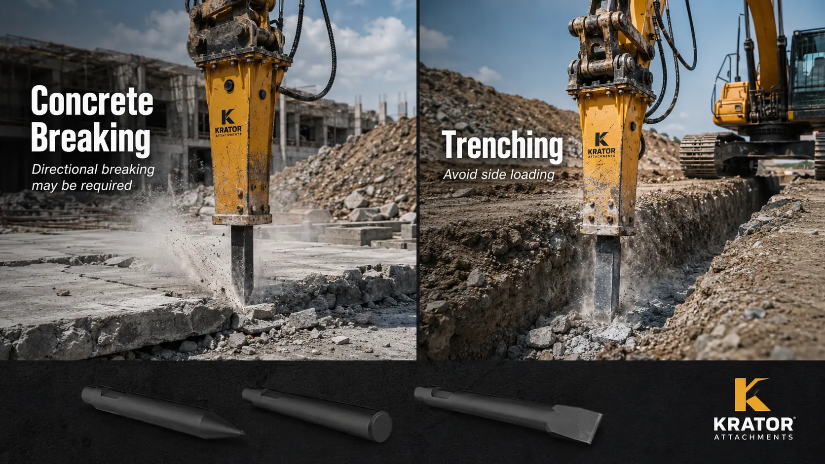
Tool Selection for Reinforced and Plain Concrete
Reinforced Concrete
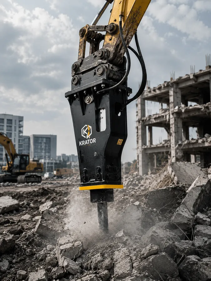
Separate the two objectives: break the concrete matrix, then manage exposed reinforcement with an approved method. A moil point may initiate penetration, while a correctly oriented flat chisel may assist controlled splitting. The breaker tool is not a substitute for a hydraulic shear used for suitable steel cutting or separation, and it should never be presented as a safe rebar cutter.
Plain Concrete
Tool choice depends on slab support, mass thickness, edges, cracking and the required break direction. A point may help penetrate a mass; a flat chisel may be considered where a directional split is useful. Confirm buried services and structural stability before work, and never use the working tool to pry separated material.
Tool Selection for Asphalt and Roadwork
A flat chisel or another model-approved cutting profile may be considered where a defined edge is useful. Asphalt thickness, base layers, temperature, buried services and access all affect the result. The cutting edge must not be twisted to lift material; stop impact and reposition the carrier.
Tool Selection for Trenching
Directional control and access are important in trenching. A flat or wedge-shaped tool may be considered for a controlled split, while a point may suit initial penetration in some compacted or frozen ground. Maintain alignment with the breaker, avoid side loading and levering, and follow the site’s utility-location and trench-safety controls.
Frozen or Compacted Ground
A pointed or approved chisel profile may help initiate cracks, but frozen layers, moisture, embedded stone and buried structures make response uncertain. Do not infer suitability from surface appearance alone.
Secondary Breaking
For separated rock or concrete, first decide whether broad crushing or crack initiation is needed. Stop striking after the piece separates, keep the carrier stable and prevent the tool from contacting loose moving material at an angle.
Tool Categories in Brief
Moil Point: Where It Is Commonly Considered
A moil point concentrates contact and is commonly considered for penetration, initiating a fracture and general breaking. It is not automatically suitable for all hard rock, and a sharp profile does not compensate for an unmatched breaker or poor placement.
Blunt Tool: Where Broad Impact May Be Useful
A blunt tool spreads contact over a broader end and may be useful for brittle oversized stone or some secondary breaking. It can be ineffective where the task requires penetration or a controlled split, and availability remains breaker-model specific.
Flat Chisel or Wedge: Directional Breaking Considerations
A flat edge may guide a split in layered material, concrete, asphalt or trenching when the edge remains correctly oriented. Never twist, lever or pry with the tool. If the direction changes, stop impact and reposition the excavator.
Why the Same Tool May Behave Differently on Different Sites
Material composition, joints, weathering, moisture, confinement, support and abrasiveness change how impact travels. Carrier flow and pressure, return conditions, oil temperature, working angle, contact stability and operating practice also affect behavior. A tool that appears suitable on one site may need reassessment on another even when both materials share the same general name.
Carrier, Flow and Breaker-Model Confirmation
Confirm the excavator model and operating weight, auxiliary flow, operating pressure, return-line requirements and exact breaker model before changing tool category. Use the hydraulic flow and pressure guide to prepare circuit data, then confirm the supported tool diameter, length, retainer geometry and any model-specific limits. The hydraulic breaker category explains the carrier and bracket information needed for model review.
A Practical 10-Step Tool-Selection Process
- Identify the material: record rock, concrete, asphalt, frozen ground or another verified material.
- Define the objective: decide whether penetration, crushing or directional splitting is required.
- Assess structure: note whether the material is massive, fractured, layered, brittle or reinforced.
- Confirm the breaker model: use the exact brand, model and nameplate, not housing appearance alone.
- Confirm available shapes: ask which working-tool profiles are approved for that breaker.
- Check carrier hydraulics: verify flow, pressure and return conditions using approved methods.
- Review position and access: confirm visibility, reach, tool angle, utilities and ground stability.
- Confirm fitment: verify retainer design and tool dimensions before ordering.
- Observe initial behavior: monitor contact stability, fracture response, vibration and abnormal movement.
- Stop and reassess: stop if impact is unstable, the tool side-loads, cracks appear or progress remains abnormal.
Common Tool-Selection Mistakes
- Choosing only from the material name without assessing structure and working objective.
- Assuming the largest or sharpest tool is automatically more effective.
- Ordering from diameter alone without model, length and retainer confirmation.
- Using a flat edge without controlling its orientation.
- Using the tool as a pry bar or continuing under side load.
- Treating concrete breaking and reinforcing-steel cutting as the same task.
- Continuing with visible cracks, abnormal deformation or unstable impact.
Signs the Selected Tool May Not Suit the Application
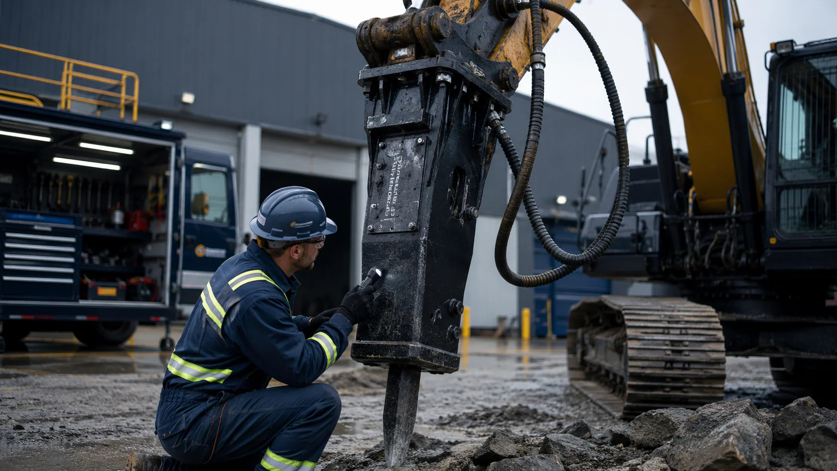
Repeated unstable contact, persistent sideways movement, unexpected rotation of a flat edge, little change after correct repositioning, abnormal vibration, repeated blank firing, rapid heat increase, visible cracking or deformation require a stop and reassessment. These signs do not prove a single cause. Use the breaker troubleshooting guide to record external evidence and separate safe checks from technician-only work.
Routine inspection and lubrication also influence tool behavior. Follow the exact equipment instructions and review the hydraulic breaker maintenance checklist. Do not weld, heat, straighten or strike a worn tool, and do not dismantle the breaker without qualified authorization.
Information to Send for Tool Matching
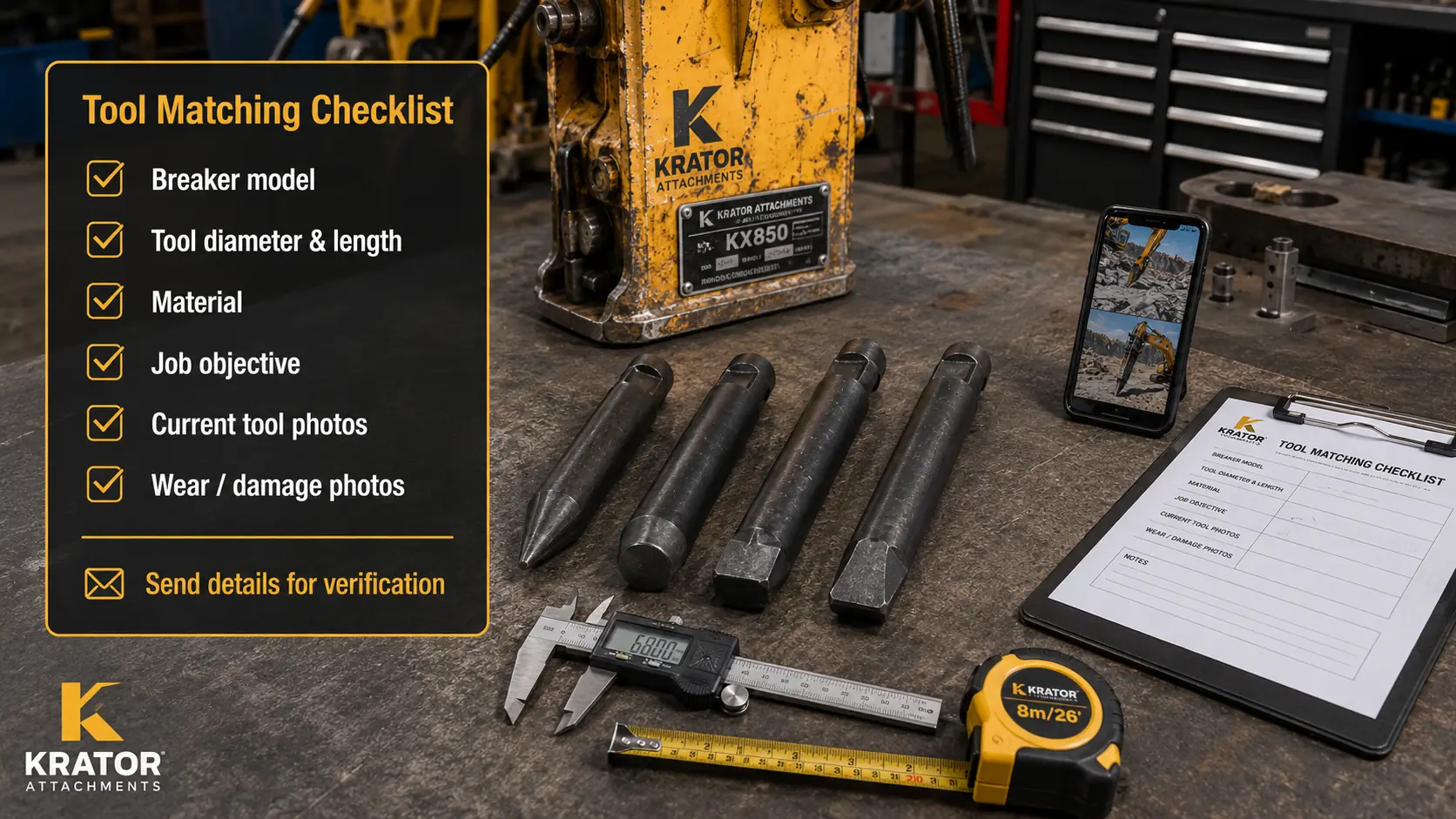
A complete request should identify the exact breaker and the job. KRATOR-specific working-tool availability, dimensions, retainer variants and model compatibility remain [BUSINESS INPUT REQUIRED]. The quality-control process can provide context for order confirmation, while exact tool inspection evidence must be approved for this article.
WORKING TOOL MATCHING
Send the breaker model and application
Working-tool availability and dimensions depend on the exact breaker model. Share the material, job objective and existing tool before ordering or changing the tool type.
Breaker
- Brand and model
- Nameplate photo
- Existing tool dimensions
Application
- Rock, concrete or trenching
- Working objective
- Material photos
Evidence
- Current tool photos
- Wear or damage photos
- Short working video