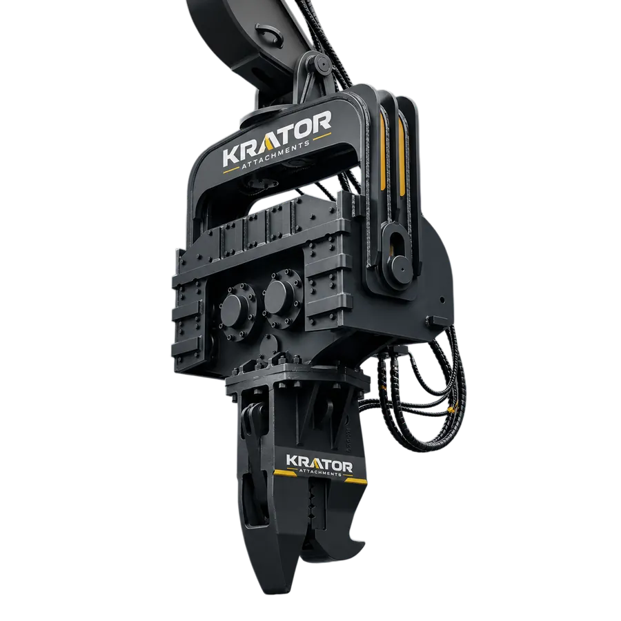

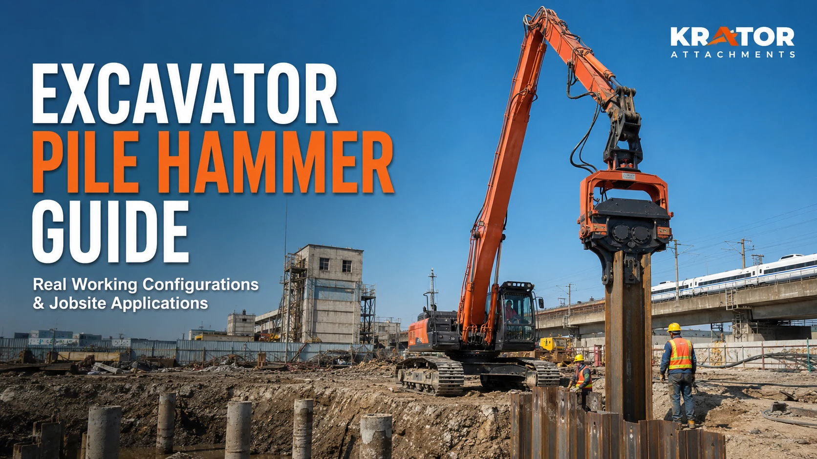
A side-grip vibratory pile hammer clamps the pile from the side and may be considered when the pile must be picked up horizontally, positioned in restricted space or started with limited overhead clearance. A top-clamp hammer engages near the pile head and is commonly considered when the pile can be presented vertically and the site supports a controlled top-handling workflow. Neither configuration is universally better. The correct choice depends on pile profile, dimensions and weight, excavator reach and hydraulics, soil, working depth, available headroom, jobsite layout and the approved jaw design.
What a Pile-Hammer Clamp Does
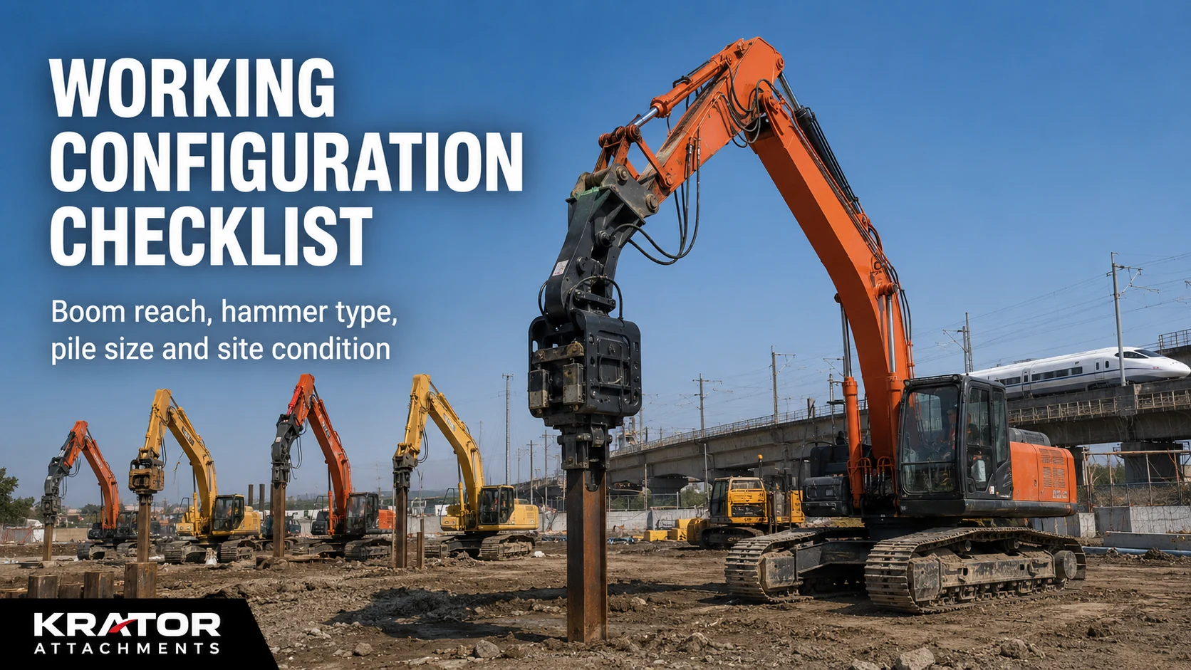
The clamp connects the vibratory hammer to the pile so vibration and handling forces can be transferred through a controlled contact area. Clamp position affects how the pile is picked up, how the excavator presents it to the driving line, what working envelope is needed and what the operator can see. It does not replace model matching. The hammer, clamp, carrier, pile and jobsite must be reviewed as one system.
The general excavator-mounted pile-hammer selection guide explains how to prepare carrier, pile, soil and hydraulic information for complete model selection. This comparison has a narrower role: deciding whether side pickup or top pickup better matches the planned handling and positioning workflow.
Side-Grip Vibratory Pile Hammer Explained
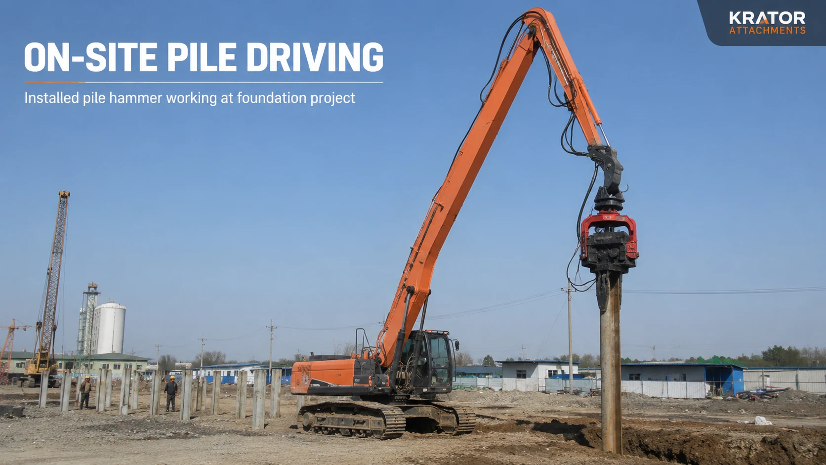
A side-grip vibratory pile hammer engages the pile along its side rather than only at the pile head. This arrangement may be considered when piles need to be picked up from a horizontal or low position, when the starting area has limited headroom, or when handling and positioning are a major part of the work cycle.
Side pickup can be useful on trench-support, riverbank or restricted urban sites where a long pile cannot easily be lifted into a fully vertical position before the hammer engages it. The excavator may be able to grip, raise, rotate and position the pile through stages. That does not make the arrangement suitable for every pile. The pile profile, jaw opening, contact area, clamp geometry, pile weight and length, carrier reach, hydraulic system, soil and approved working procedure all require review.
Top-Clamp Vibratory Pile Hammer Explained
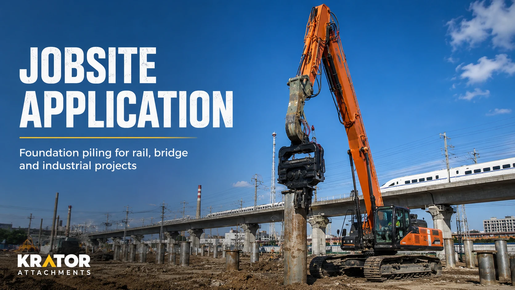
A top-clamp vibratory pile hammer engages the pile near its upper end. It is commonly considered when the pile can be positioned vertically before or during engagement, the project has adequate overhead clearance and the work sequence prioritizes controlled vertical alignment.
The arrangement may suit a straightforward driving line where lifting equipment, the excavator working position and site access allow the pile to be presented safely. Final suitability still depends on the pile profile and dimensions, jaw design, excavator configuration, hydraulic capacity, working depth, soil and operating plan. A top clamp is not automatically compatible with every sheet pile, post or structural section.
Side Grip vs Top Clamp: Main Differences at a Glance
| Selection Factor | Side Grip | Top Clamp | Information Requiring Confirmation |
|---|---|---|---|
| Clamp position | Contacts the pile along the side at an approved pickup area. | Engages near the pile head or approved top position. | Pile cross-section, contact area and clamp orientation. |
| Pile pickup method | May pick up a pile from a horizontal or low position. | Commonly uses a pile already presented toward vertical. | Pile weight, lifting plan, pickup point and site procedure. |
| Initial pile positioning | Can support staged lifting and rotation where geometry permits. | Favors a controlled vertical presentation and driving line. | Excavator reach, working angle and available support equipment. |
| Working headroom | May be considered where vertical starting clearance is restricted. | Usually needs clearance above the pile for the hammer and carrier. | Measured headroom, pile length and excavator position. |
| Excavator reach | Reach is used for pickup, rotation, positioning and driving. | Reach is used mainly to maintain the top engagement and driving line. | Boom and arm geometry, mounting height and working radius. |
| Vertical alignment | Requires a planned transition from pickup position to driving line. | Commonly supports a directly vertical workflow once engaged. | Pile tolerance, site control method and operator visibility. |
| Sheet-pile handling | May assist side pickup and positioning of verified profiles. | May suit sheet piles that can be presented vertically to the top jaw. | Interlock profile, jaw contact area, width and thickness. |
| Confined jobsite use | May help when trench edges, structures or utilities restrict lifting space. | May work where the vertical line is clear and overhead space is adequate. | Site plan, exclusion zones, obstructions and carrier access. |
| Pile-profile compatibility | Depends on side contact geometry and gripping surface. | Depends on head profile and available top-jaw geometry. | Cross-section drawing, photos, dimensions and material. |
| Jaw configuration | May require profile-specific side jaws or contact inserts. | May require a profile-specific top jaw or head interface. | Opening requirement, contact area and approved drawing. |
| Hydraulic requirements | Hammer, clamp functions and carrier circuit must be checked together. | Hammer, top clamp and carrier circuit must be checked together. | Model-specific oil flow, pressure, auxiliary lines and controls. |
| Transport and setup | Additional clamp geometry and handling procedure may affect setup. | Site preparation may need a reliable way to present the pile vertically. | Transport dimensions, setup method and local lifting plan. |
| Operator visibility | Visibility can change during pickup, rotation and final alignment. | Visibility centers on the top engagement and vertical driving line. | Cab position, camera support, spotter plan and obstructions. |
| Typical project workflow | Pickup, grip, raise, rotate, position, align and drive. | Present, engage at the top, align and drive. | Actual method statement, pile staging and site sequence. |
Pile Pickup and Positioning Workflow
Workflow is often the clearest difference between the two clamp types. A side-grip setup may reduce the need to place the pile fully upright before engagement, but it adds a controlled transition from the pickup position to the driving line. A top-clamp setup may use a simpler engagement sequence once the pile is vertical, but the site must first support that vertical presentation.
- Record how piles will arrive, be stored and be presented to the excavator.
- Confirm whether the hammer must pick up the pile or only engage it after another controlled positioning step.
- Map the excavator position, working radius, trench edge, overhead restrictions and nearby structures.
- Confirm the approved gripping area and orientation on the pile drawing.
- Review the complete sequence with the exact carrier, hammer, clamp and pile before model confirmation.
Limited-Headroom and Confined-Space Considerations
A side-grip configuration is commonly considered for limited-headroom projects because it may pick up and begin positioning a long pile without first raising the entire pile above the driving point. This can matter beneath bridges, near overhead structures, beside buildings or in restricted trench corridors. The available envelope still needs to include the excavator, attachment rotation, pile swing, safe clearances and the final driving line.
A top-clamp configuration may be practical on a confined site when the vertical line is clear and the pile can be presented safely. “Confined” does not automatically mean side grip, and “open” does not automatically mean top clamp. Measured headroom and a site layout are more useful than a general site description.
Vertical-Driving Considerations
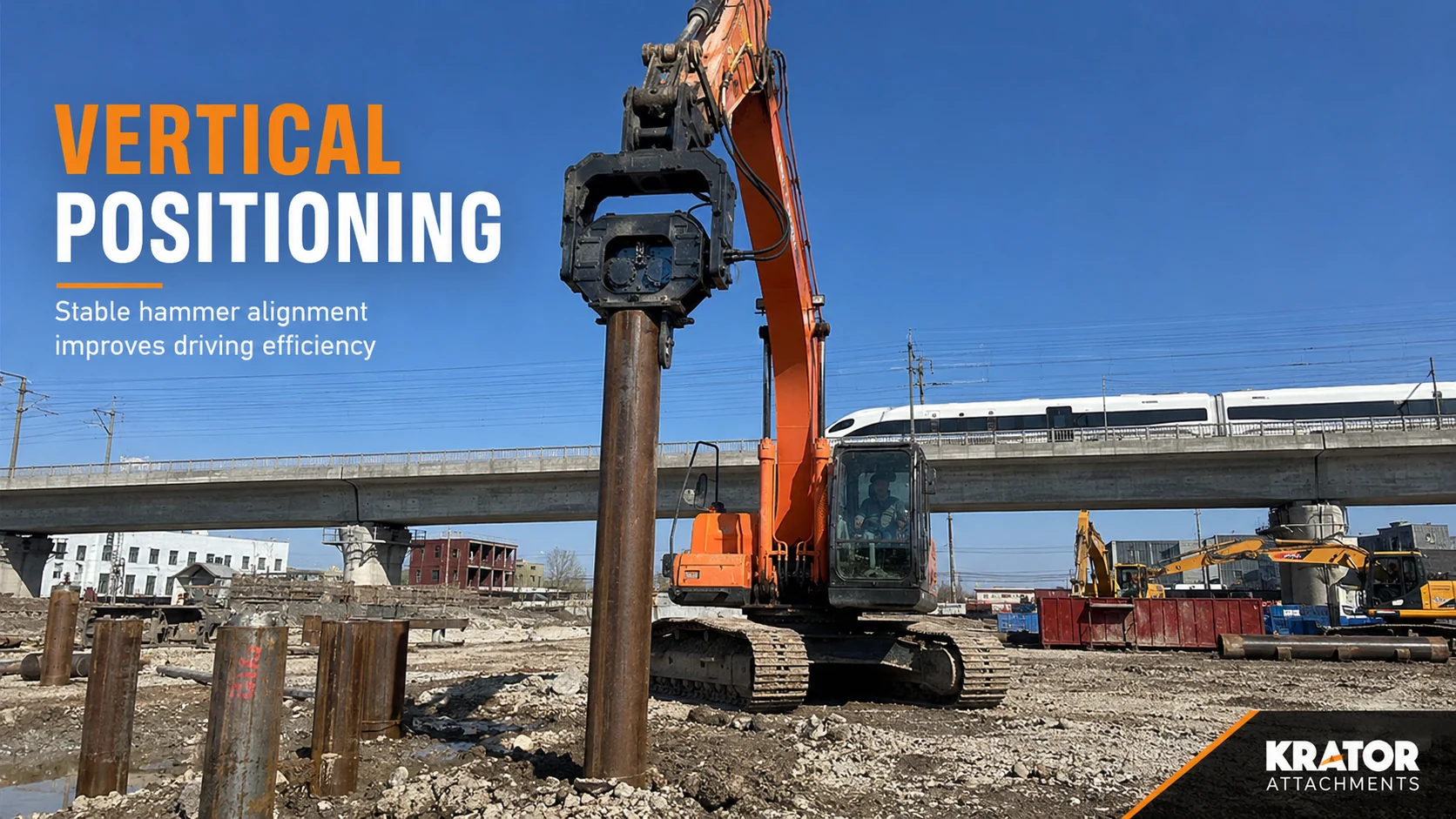
Vertical alignment depends on more than clamp position. Carrier stability, boom and arm angle, attachment mounting geometry, pile straightness, soil resistance and the operator's view all affect control. A top clamp can support a direct vertical workflow when the pile is already presented correctly. A side grip can also move into a vertical driving position, but the transition and approved grip location must be reviewed.
Neither configuration should be selected from a promotional photo alone. Provide a side view of the excavator position, planned working radius and pile line so the technical review can evaluate reach and orientation.
Sheet-Pile Handling Considerations
Steel sheet piles vary in interlock, width, thickness and section geometry. Side-grip and top-clamp arrangements may both be considered for sheet-pile work, but the jaw must contact an approved area without relying on an assumed universal profile. Riverbank, trench-support and temporary retaining projects can also impose different pickup, alignment and working-space constraints.
Send the manufacturer drawing or a clear cross-section, overall pile dimensions and close-up photos of the interlock and proposed gripping area. Do not describe a pile only as “standard sheet pile.”
Guardrail, Solar-Pile and Steel-Post Applications
Guardrail posts, solar piles and steel posts can have narrow, open or shaped sections that differ from sheet piles. Either clamp concept may be reviewed when the jaw design and pickup method suit the exact section. A smaller post does not automatically require a simpler jaw, and appearance alone does not confirm adequate contact.
Provide the profile drawing, material and dimensions, pile length, approximate weight where safely available, planned pickup point and required orientation. Driving performance and soil suitability remain project-specific.
Trench-Support and Foundation Applications
Trench-support work often adds restrictions from excavation edges, bracing, utilities, access roads and adjacent structures. Side pickup may help when piles are staged beside the trench, while a top clamp may suit a prepared vertical handling sequence. Foundation-support work on an open site may offer more carrier positioning options, but depth, soil and pile geometry still govern the review.
For an initial equipment overview, see the excavator-mounted pile driver. The product name alone does not confirm which clamp arrangement fits a particular trench or foundation plan.
Excavator Reach and Working-Angle Considerations
The carrier must manage the pile and hammer through the full work sequence, not only at the final driving point. Side-grip work can use additional reach during pickup and rotation. Top-clamp work may require sufficient height and working radius above a vertical pile. Boom, arm and mounting photos help show whether the real machine configuration matches the assumed envelope.
Do not confirm a clamp using excavator tonnage alone. The exact model, operating weight, boom and arm arrangement, attachment mounting position and planned excavator stance are required.
Jobsite Visibility and Pile Control
Operator visibility changes through pickup, lifting, alignment and driving. With side grip, the operator may need to monitor the side contact and the pile's rotation into position. With top clamp, the top engagement and vertical driving line are important. Cab position, nearby structures, trench depth and pile length can create blind areas for either configuration.
Site photos and a short video of the proposed excavator position help technical review. The project's operating and communication procedure must be established by the responsible jobsite team; this article does not replace a site-specific method statement.
Pile-Profile and Jaw-Shape Requirements
Jaw selection begins with the pile cross-section. Sheet piles, H-beams, steel posts, solar piles, guardrail posts, timber piles and custom structural sections do not share one universal contact geometry. The jaw must be reviewed for opening, contact area, orientation, pickup position and the forces expected in the approved workflow.
Timber piles should be considered only when the exact pile and a verified jaw arrangement are approved. Surface condition, section variation and risk of local damage require project-specific review.
Hydraulic and Auxiliary-Circuit Requirements
The hammer and clamp functions must be matched to the excavator's hydraulic system. Provide hydraulic oil flow, operating pressure, available auxiliary lines, return arrangement, hose and fitting information and current control details. The required circuit may differ by hammer model and clamp configuration.
Use the hydraulic flow and pressure guide to prepare carrier data, but do not substitute general ranges for model-specific confirmation. Exact side-grip and top-clamp hydraulic requirements remain subject to KRATOR technical review.
When a Custom Jaw May Be Required
A standard jaw may not suit every sheet-pile profile, H-beam, steel post, solar pile, guardrail post, timber pile or custom structural section. A custom jaw may be reviewed when the cross-section, opening, contact area, pickup position or required orientation differs from the available standard arrangement.
Provide a dimensioned pile drawing and identify the intended contact and pickup positions. KRATOR must review geometry, manufacturability, connection points, hydraulic controls and the complete operating method. Not every custom request is feasible. See the custom excavator attachments page for the project information needed before an engineering discussion.
Before model-specific claims can be published, KRATOR needs an approved side-grip and top-clamp model list, jaw-opening ranges, clamp-force data, verified pile-profile matrix, model-specific hydraulic requirements, standard-versus-custom jaw rules and any public operating limitations. These items are intentionally not presented as confirmed specifications in this guide.
Project Comparison: Which Clamp Is Commonly Considered?
| Project | Common Pile Type | Clamp Configuration Commonly Considered | Why | Main Limitation | Evidence Required |
|---|---|---|---|---|---|
| Steel sheet piles | Interlocking steel sheet sections | Side grip or top clamp | Choice follows pickup method, headroom and profile contact. | Interlocks and section geometry vary. | Profile drawing, width, thickness, length and pickup plan. |
| Trench-support piles | Sheet piles, beams or posts | Side grip commonly reviewed; top clamp also possible | Side pickup may help where trench access is restricted. | Bracing, utilities and edge distance can limit movement. | Trench layout, site photos, depth and excavator position. |
| Riverbank sheet piles | Steel sheet piles | Side grip or top clamp | Staging area and carrier access often determine handling. | Slopes, water edge and reach affect the work envelope. | Site plan, bank profile, pile drawing and carrier position. |
| Solar piles | Open or formed steel sections | Project-specific side or top jaw | Profile and orientation determine the contact method. | Narrow sections may need dedicated jaw geometry. | Cross-section, dimensions, length, material and layout. |
| Guardrail posts | Formed steel posts | Project-specific side or top jaw | Repeated post alignment may guide the workflow. | Post shapes are not universally interchangeable. | Profile drawing, post length, spacing and soil information. |
| Steel posts | Pipe, box, H or custom sections | Side grip or top clamp after profile review | Pickup point and vertical presentation vary by section. | Contact area and local deformation require review. | Section drawing, wall thickness, weight and handling plan. |
| Timber piles where verified | Round or prepared timber piles | Only an approved project-specific jaw | Material variability requires cautious contact design. | Surface condition and local damage risk. | Diameter range, material condition, length and approved method. |
| Foundation support work | Sheet piles, posts or beams | Side grip or top clamp | Open access may support several handling sequences. | Soil, depth and pile mass still govern equipment matching. | Geotechnical summary, depth, pile data and carrier details. |
| Confined urban jobsites | Project-specific support piles | Side grip commonly considered | May reduce the vertical clearance needed at initial pickup. | Structures and exclusion zones can still restrict rotation. | Measured headroom, site video, plan and pile staging method. |
| Open foundation sites | Sheet piles, beams or posts | Top clamp or side grip | More space can support either verified workflow. | Open space does not resolve pile or hydraulic mismatch. | Pile drawing, soil, depth, machine data and method statement. |
PILE HAMMER CLAMP MATCHING
Send the excavator, pile and jobsite information
Side-grip or top-clamp selection depends on the pile profile, excavator hydraulics, available working space and required handling method. Share the information below before confirming a configuration.
Excavator brand and model
Operating weight
Hydraulic flow and pressure
Pile type and profile
Pile size and length
Drawing or clear photos
Soil condition
Required depth
Headroom and working-space photos
Common Clamp-Selection Mistakes
- Choosing only from excavator tonnage.
- Not confirming the pile profile or proposed contact area.
- Ignoring measured headroom and working-space restrictions.
- Assuming all sheet piles use the same jaw.
- Omitting pile length, approximate weight and pickup method.
- Ignoring hydraulic oil flow, operating pressure and auxiliary-line information.
- Failing to provide soil condition and required driving depth.
- Choosing side grip only because it appears more flexible.
- Choosing top clamp without confirming how the pile will be positioned vertically.
- Ordering before drawings, photos and the work sequence are reviewed.
- Assuming a jaw can be transferred between unrelated pile profiles.
Side Grip Is Not Automatically Better
Side grip can add valuable handling options, particularly when piles start horizontally or headroom is restricted. It can also introduce more pickup, rotation and alignment steps. If the site already supports a controlled vertical presentation, the extra side-handling capability may not be necessary. The decision should follow the work sequence and verified equipment data, not the appearance or perceived flexibility of the clamp.
Top Clamp Is Not Automatically Simpler
A top clamp can support a direct vertical driving workflow, but the project still needs a reliable way to present and stabilize the pile, enough overhead clearance, a suitable jaw and a carrier that can maintain the required position. Top engagement does not remove the need to confirm pile geometry, hydraulics, soil, reach or jobsite control.
Information Required Before Model Confirmation
Excavator brand, exact model, operating weight, hydraulic oil flow, operating pressure, auxiliary-line information and arm and boom photos.
Pile type, profile, width, thickness, length, approximate weight where safely available, drawing or cross-section, pickup method and driving method.
Soil condition, required depth, available headroom, working space, excavator position, trench or foundation layout, site photos and video.
The fast attachment quote checklist can help purchasing teams organize the submission. Model confirmation must wait until the exact pile and project data have been reviewed.
Dealer and Rental-Fleet Considerations
Dealers and rental fleets should keep model-specific records rather than treating every pile hammer or clamp as interchangeable. Record carrier hydraulic data, approved clamp configurations, pile-profile drawings, jaw identification, wear-part references, hose details and photos of previous installations. Keep quotation records tied to the exact machine and project.
Before transferring equipment between excavators, recheck the carrier, mounting, hydraulic circuit and controls. Prepare appropriate spare hoses and verified wear parts for the supported configurations. A previous installation photo is useful evidence, but it does not prove compatibility with an unrelated carrier or pile profile.
KRATOR's visible manufacturing and quality-control process provides supplier context, while final clamp suitability remains a technical review for the order.